
lifuyan78@gmail.com
18822971180
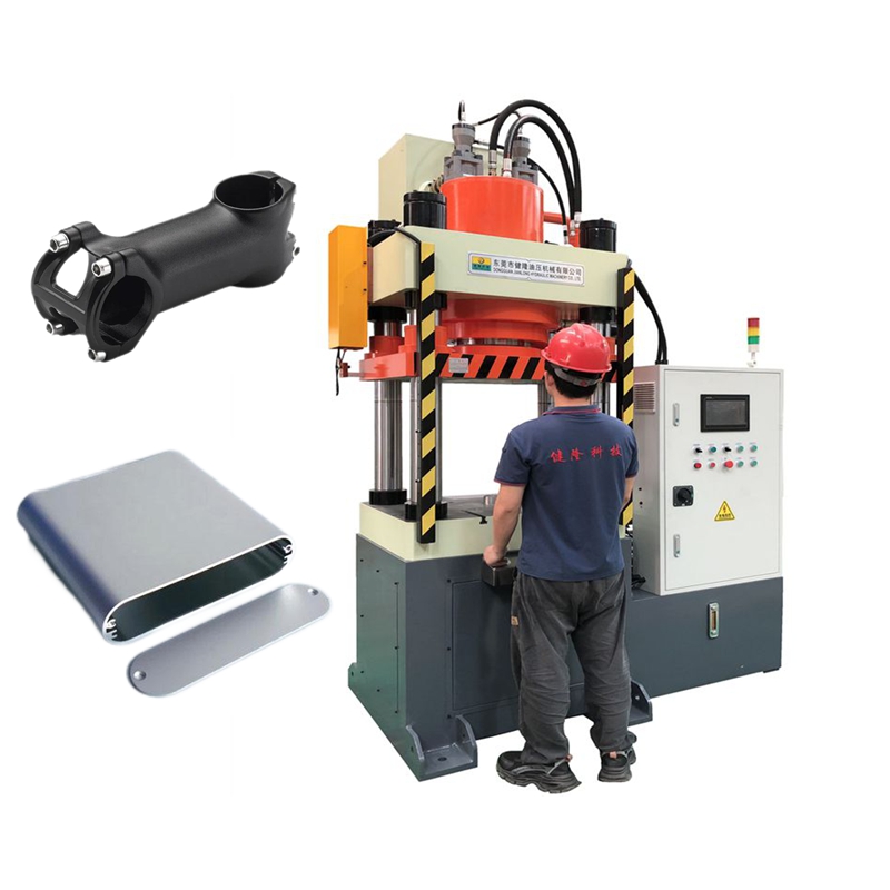
Adjusting the slide stroke on a forging hydraulic press primarily involves controlling the slide's upper and lower limit positions (Top Dead Center/Bottom Dead Center) to accommodate different die heights and forging processes. The four mainstream adjustment methods are: electronic digital setting, mechanical limit stops, hydraulic valve control, and die-height fine-tuning. Below, the team at Jianlong Hydraulic Technology shares the detailed operating procedures and underlying principles for your reference.
1. Safety preparations before adjustment (Mandatory)
1.1 Shut down the machine, disconnect the power, hang a warning sign, and press the emergency stop button.
1.2 Manually jog the slide to Top Dead Center (TDC) and clear the worktable and die area.
1.3 Prepare a dial indicator, calipers, and specialized wrenches; verify the parameters in the equipment manual.
2. Mainstream adjustment methods and operating steps
2.1 Electronic digital setting (Servo/PLC models; most common)
2.1.1 Application: Precision forging hydraulic presses equipped with touchscreens, PLCs, and displacement sensors (optical or magnetic scales).
2.1.2 Principle: Directly set the slide stroke and the positions of the Top and Bottom Dead Centers via the control system.
2.1.3 Operation:
1)Access the equipment interface and locate the "Stroke Setting" or "Die Height" menu.
2)Input the target total stroke (e.g., 400mm), the Bottom Dead Center position (which determines the die-closing depth), and the Top Dead Center position.
3)The system performs an automatic check and activates closed-loop control (using real-time feedback from displacement sensors).
4)Conduct a no-load jog test; measure the actual stroke with a dial indicator and fine-tune parameters to bring them within tolerance (±0.02–0.1mm).
5)Save the process parameters and lock the interface.
2.2 Mechanical limit block adjustment (Traditional/Economical models)
2.2.1 Application: hydraulic presses without precision electronic controls that rely on mechanical contact for limiting travel.
2.2.2 Principle: Adjust the spacing between the upper and lower limit blocks (strikers) on the columns; the slide stops upon contact.
2.2.3 Operation:
1)Loosen the locking bolts on the limit blocks and reposition the upper and lower limit blocks.
2)Use a ruler to measure the distance between the two trip dogs; this distance represents the slide's working stroke.
3)Tighten the bolts and perform "inch" (jog) tests to ensure the trip dogs trigger reliably and do not come loose.
4)Suitable for coarse adjustment; precision is relatively low (±0.5–1 mm).
2.3 Stroke Control via Hydraulic Valve Assembly (Some older models)
2.3.1 Application: Equipment lacking displacement sensors that relies on hydraulic valves to control flow or flow direction (reversing).
2.3.2 Principle: Adjust the stroke-limiting throttle valve and directional control valve to regulate the oil cylinder's intake volume and the timing of flow reversal.
2.3.3 Operation:
1)Locate the stroke adjustment valve on the hydraulic power unit (usually marked with a scale).
2)Turn clockwise to reduce opening → shorten stroke; turn counter-clockwise to increase opening → lengthen stroke.
3)Perform repeated inching tests in conjunction with limit switches until the stroke meets requirements.
4)Disadvantages: Poor precision and prone to drift; suitable for simple forging operations.
2.4 Die Shut Height / Connecting Rod Fine Adjustment (High-end multi-directional forging presses)
2.4.1 Application: Precision models equipped with eccentric sleeves, adjustment screws, or wedge mechanisms.
2.4.2 Principle: Fine-tune the connection length between the slide and the cylinder to alter the Bottom Dead Center (BDC) position (without changing the total stroke).
2.4.3 Operation:
1)Loosen the locking nut or wedge mechanism at the top of the slide.
2)Use a wrench to rotate the adjustment screw or eccentric sleeve:
·Clockwise → BDC moves up → die shut height decreases;
·Counter-clockwise → BDC moves down → die shut height increases.
3)Monitor BDC changes using a dial indicator; refer to the manual for the stroke distance corresponding to each full rotation.
4)Lock the mechanism securely to prevent displacement caused by forging vibrations.
3. Key Adjustment Points for Stem Forging
3.1 Cold Forging vs. Warm Forging: Cold forging requires stroke repeatability of ≤0.05 mm, prioritizing electronic control with closed-loop feedback; warm forging allows for slightly looser tolerances but requires compensation for thermal expansion. 3.2 Multi-directional forging: The vertical main stroke and horizontal side cylinder strokes must be synchronized to ensure uniform metal filling.
3.3 Die matching: Stroke = Die shut height + Billet height + Safety margin (10–20 mm).
3.4 Dwell and return: After adjustment, check the dwell position and return speed to prevent impact/shock.
4. Commissioning and verification process
4.1 Perform 3–5 dry-run (no-load) jog cycles; observe the slide for smooth operation and ensure there is no binding or sticking.
4.2 Measure the Top Dead Center (TDC) and Bottom Dead Center (BDC) positions using a dial indicator and record the actual stroke.
4.3 Perform a trial forging with a billet; inspect the forming quality and flash size.
4.4 Run a continuous production batch of 20–50 pieces; spot-check dimensions to confirm stroke stability.
5. Common issues and solutions
5.1 Inaccurate stroke / Drift: Check the displacement sensor, locking mechanism, and for internal leakage in hydraulic valves.
5.2 BDC too deep / too shallow: Fine-tune the die shut height and reset the BDC position.
5.3 Jammed press (slide stuck at BDC): Use the eccentric sleeve or hydraulic release mechanism to lift the slide and increase the die shut height.
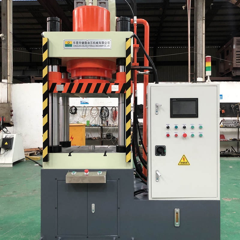
Would you like us to generate a ready-to-use adjustment procedure and parameter record sheet tailored to your specific machine type (servo vs. conventional) and target stroke/die shut height? Please contact us. Jianlong Hydraulic Technology currently offers Custom hydraulic presses ranging from 10 to 5,000 tons (including supporting automation lines, chillers, air compressors, etc.). All presses are CE certified and fully compliant with the EU Machinery Directive (2006/42/EC); our products are exported to markets in Europe and the Americas, including Germany, the USA, Mexico, and Portugal. If you have any questions or purchasing requirements, please contact us (or scan the WhatsApp QR code below); Jianlong Hydraulic Technology is dedicated to providing you with personalized, customized professional solutions.

Contact: Jojo
Phone: 18822971180
E-mail: lifuyan78@gmail.com
Whatsapp:+8618822971180
Add: Guangyi Industrial Park, No.2 Jinfu West Road, Tanglip, Liaobu Town, Dongguan City, Guangdong Province, China
We chat